Traffic-Light Controller
Summary
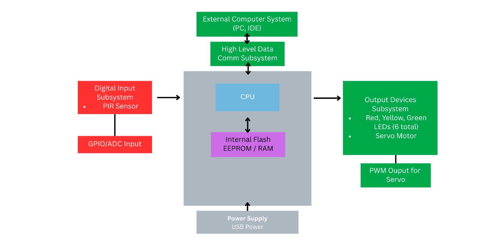
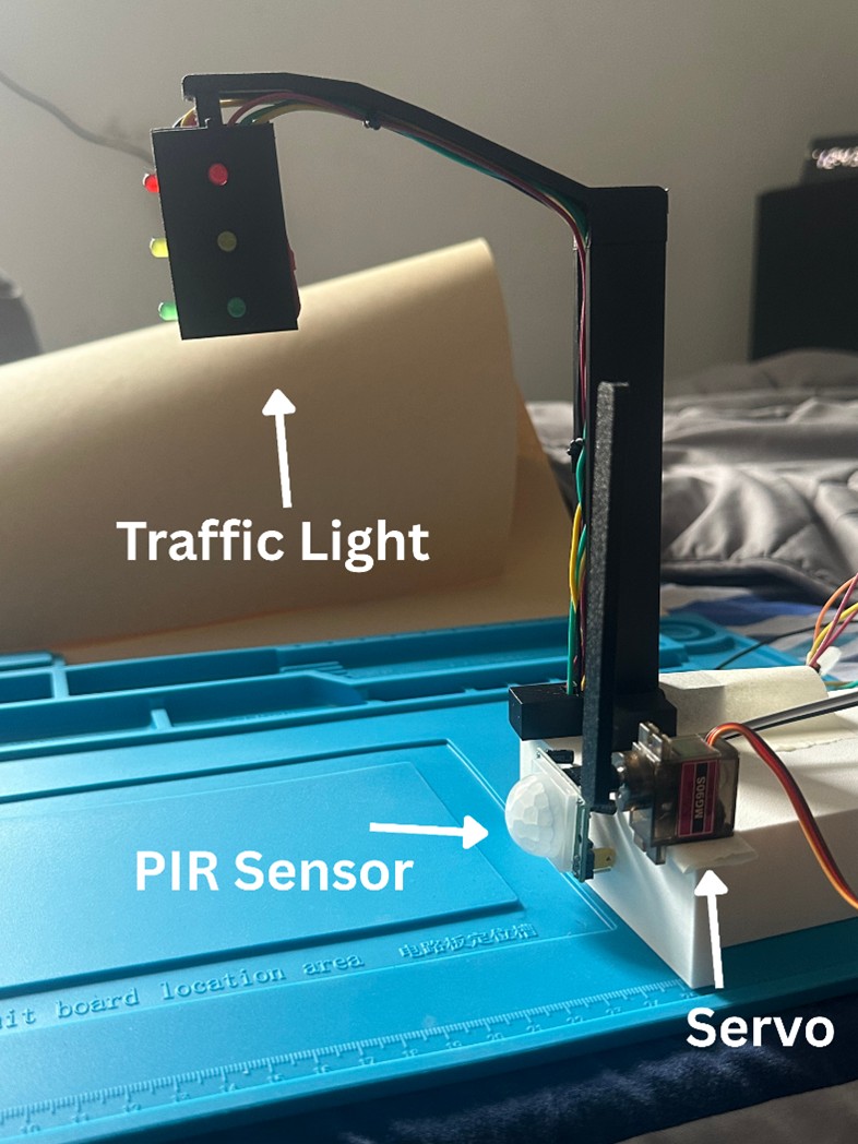
Finite-state-machine intersection controller with timed phases and debounced inputs. The design drives dual three-LED signals (Main & Side), reads a PIR sensor on the side road, and actuates a servo-powered barricade to control a gate.
Highlights
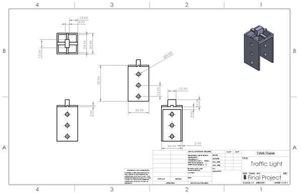
- Modeled and printed a traffic signal housing to secure LEDs and cable routing
- Functional control loop from PIR sensor read to LED state changes and servo actuation
- Debounce/edge-detect logic and timing for safe state transitions
- Basic verification of timing and sequencing using a test harness
Procedure
Preparation
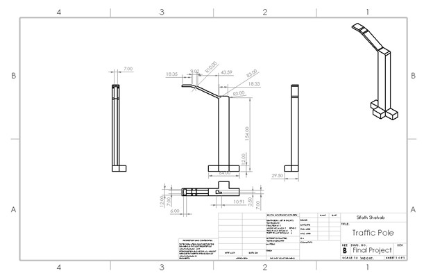
- Design a 3D model that satisfies the needs for the project. Include correctly sized slots for each LED so they slide in and are held in place, and space to house wiring.
- Print the finished model and test-fit all parts to confirm fitment is correct.
- Model and print a barricade that will fit over the servo to open and close the gate.
Part A (Hardware)
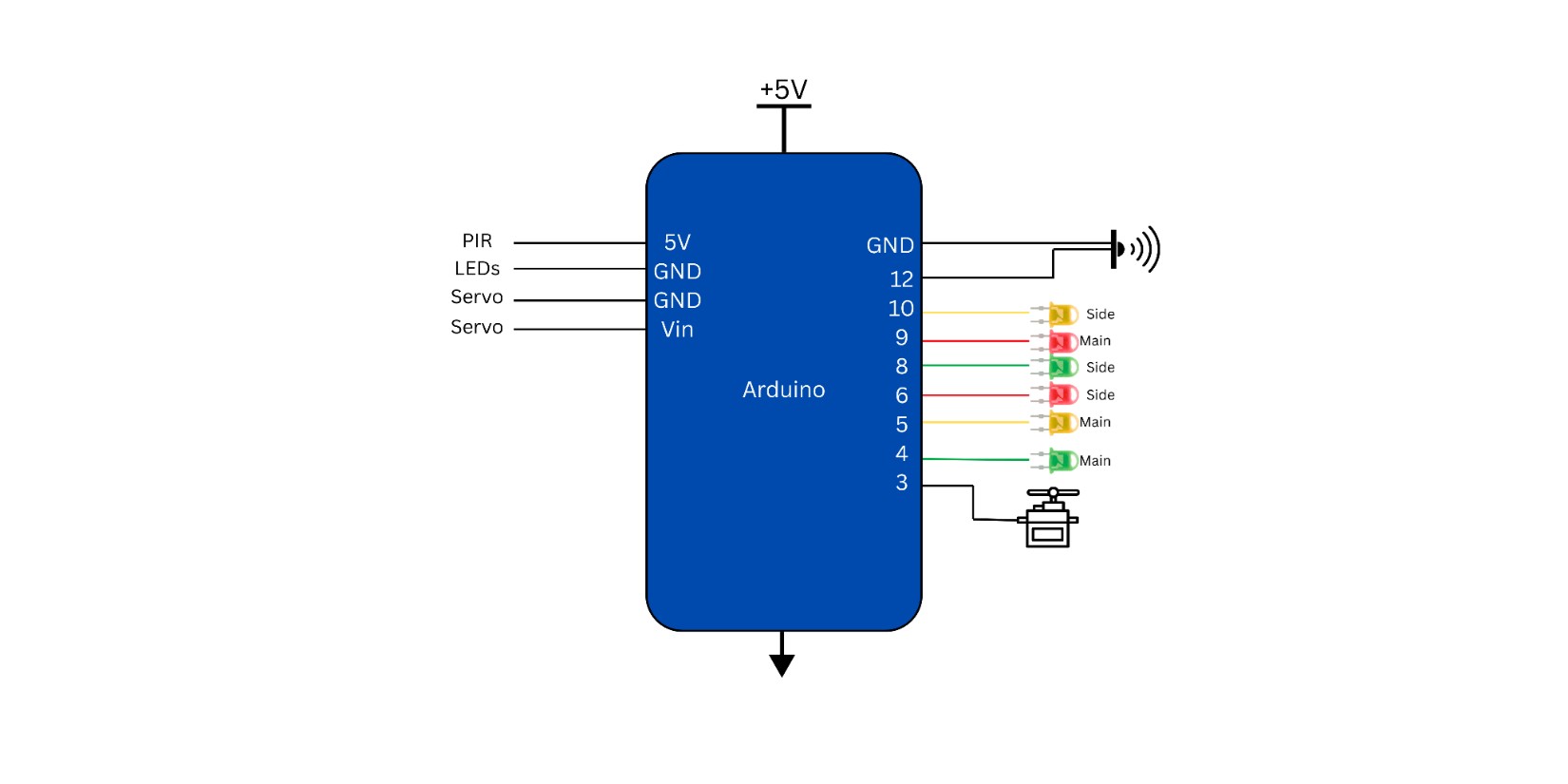
- Fit each LED in order (red top, yellow middle, green bottom). Bend all negative LED legs together and solder them into a single common ground lead shared by all six LEDs. Solder a ground cable to the single remaining ground leg.
- Solder custom-cut cables for each LED and label them. One row is “Main” and the other row is “Side.”
- Connect the labeled LED wires to specific Arduino pins and record the mapping.
- Connect the shared ground cable to an Arduino GND pin.
- Wire the PIR sensor per spec: 5V, GND, and signal → Arduino input pin.
- Attach the servo connections: GND, Vin, and signal → Arduino.
- Mount the PIR sensor securely. Attach the 3D-printed barricade to the servo and mount the servo so 0° is the upright position.
Part B (Software)
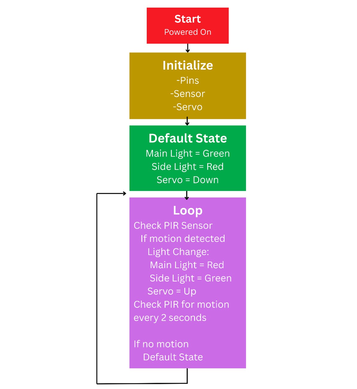
- Write the control program: Main light stays green until the PIR sensor is triggered on the side road. After a short delay, switch Main → red and Side → green; raise the servo (open barricade).
- Implement a delay after motion stops to allow traffic to clear. Then switch Side → red and Main → green, and lower the barricade.
- Verify all pin constants in code match your recorded LED and sensor/servo wiring so sequences run correctly.
Project Media
© Sifath Shahab